Showing posts with label Electrical Machine. Show all posts

Saturday, 19 December 2015

Electrical Machine Interview Question And Answer

[1] Define the term synchronous speed [Dec-2003]
For synchronous machines there exists a fixed relationship between number of poles P, frequency (f) and the speed of the machine. The speed of the synchronous machine for the given number of poles and the rated frequency is called the synchronous speed mentioned as NS.

[2] Write an expression for synchronous speed (Dec-2004)
An expression for synchronous speed is NS = 120f/P.
Where
f = frequency
P = No of poles of the machine.

[3] What does speed voltage mean? (Dec-2007)
When the magnetic flux is constant as well as stationary and the coil rotates to cut the flux then EMF gets induced due to relative speed between flux and coil. This EMF is called speed EMF, rotational EMF or dynamically induced EMF.

[4] Mention the factors on which hysteresis loss depends (Dec-2008)
The hysteresis loss is directly proportional to the area under the hysteresis curve ie area of the hysteresis loop.
It is directly proportional to frequency ie number of cycles of magnetization per second.
It is directly proportional to volume of the material.

[5] Distinguish between statically induced and dynamically induced EMF (Dec - 2010, 2011, 2009)
How is EMF induced dynamically ( May-2010)
An induced EMF which is due to physical movement of coil, conductor with respect to flux or movement of magnet with respect to stationary coil, conductor is called dynamically induced EMF or motional induced EMF.
The change in flux lines with respect to coil can be achieved without physically moving the coil or the magnet. Such induced emf in a coil which is without physical movement of coil or a magnet is called statically induced EMF.

[6] Define torque (May-2010)
A turning or a twisting force about an axis is called as torque.

[8] What are the three types of basic rotating electric machines? (May-2011)
DC machines
Induction Machines
Synchronous Machines

[9] What are the causes of core loss? what are the components of core loss?
When a core is subjected to an alternating flux then it undergoes the cycles of magnetisation and demagnetisation. This produces hysteresis effect which causes hysteresis loss in the core.
Similarly core is under the influence of the changing flux and under such condition according to the Faraday's law of electromagnetic induction, EMF gets induced in the core. Such currents in the core which are due to induced emf in the core are called as eddy current loss. Thus eddy current and hysteresis are the two components of the core loss.

Saturday, 6 June 2015

Construction of a DC Machine And working of dc motor

As stated earlier, whether a machine is d.c. generator or a motor the construction basically remains the same as shown in the Fig. 1.
Fig.1 A cross section of typical d.c. machine
It consists of the following parts :
1.1 Yoke
a) Functions :
  1. It serves the purpose of outermost cover of the d.c. machine. So that the insulating materials get protected from harmful atmospheric elements like moisture, dust and various gases like SO2, acidic fumes etc.
  2. It provides mechanical support to the poles.
  3. It forms a part of the magnetic circuit. It provides a path of low reluctance for magnetic flux. The low reluctance path is important to avoid wastage of power to provide same flux. Large current and hence the power is necessary if the path has high reluctance, to produce the same flux.
b) Choice of Material : To provide low reluctance path, it must be made up of some magnetic material. It is prepared by using cast iron because it is cheapest. For large machines rolled steel, cast steel, silicon steel is used which provides high permeability i.e. low reluctance and gives good mechanical strength.
1.2 Poles
       Each pole is divided into two parts namely, I) Pole core and II) Pole shoe.
       This is shown in the Fig. 2.
Fig. 2 Pole Structure
a) Functions of pole core and pole shoe :
  1. Pole core basically carries a field winding which is necessary to produce the flux.
  2. It directs the flux produced through air gap to armature core, to the next pole.
  3. Pole shoe enlarges the area of armature core to come across the flux, which is necessary to produce larger induced e.m.f. To achieve this, pole shoe has been given a particular shape. 
b) Choice of Material : It is made up of magnetic material like cast iron or cast steel. As it requires a definite shape and size, laminated construction is used. The laminations of required size and shape are stamped together to get a pole which is then bolted to the yoke.
1.3 Field Winding (F1-F2)
       The field winding is wound on the pole core with a definite direction.
a) Functions : To carry current due to which pole core, on which the field winding is placed behaves as an electromagnet, producing necessary flux.
       As it helps in producing the magnetic field i.e. exciting the pole as an electromagnet it is called Field winding or Exciting winding.
b) Choice of material : It has to carry current hence obviously made up of some conducting material. So aluminium or copper is the choice. But field coils are required to take any type of shape and bend about pole core and copper has good pliability i.e. it can bend easily. So copper is the proper choice.
Note : Field winding is divided into various coils called field coils. These are connected in series with each other and in such a direction around pole cores, such that alternate 'N' and 'S' poles are formed.
       By using right hand thumb rule for current carrying circular conductor, it can be easily determined that how a particular core is going to behave as 'N' or 'S' for a particular winding direction around it. The direction of winding and flux can be observed in the Fig 3. 
Fig. 3
1.4 Armature 
       It is further divided into two parts namely,
I) Armature core and II) Armature winding
I) Armature core : Armature core is cylindrical in shape mounted on the shaft. It consists of slots on its periphery and the air ducts to permit the air flow through armature which serves cooling purpose.
a) Functions :
  1. Armature core provides house for armature winding i.e. armature conductors.
  2. To provide a path of low reluctance to the magnetic flux produced by the field winding.
b) Choice of Material : As it has to provide a low reluctance path to the flux, it is made up of magnetic material like cast iron or cast steel.
       It is made up of laminated construction to keep eddy current loss as low as possible. A single circular lamination used for the construction of the armature core is shown in the Fig. 4.
Fig. 4 Single Circular lamination of Armature core
II) Armature winding : Armature winding is nothing but the interconnection of the armature conductors, placed in the slots provided on the armature core periphery. When the armature is rotated, in case of generator, magnetic flux gets cut by armature conductors and e.m.f. gets induced in them.
a) Functions :
  1. Generation of e.m.f takes place in the armature winding in case of generators.
  2. To carry the current supplied in case of d.c. motors.
  3. To do the useful work in the external circuit. 
b) Choice of material : As armature winding carries entire current which depends on external load, it has to be made up of conducting material, which is copper.
       Armature winding is generally former wound. The conductors are placed in the armature slots which are lined with tough insulating material.
1.5 Commutator 
We have seen earlier that the basic nature of e.m.f. induced in the armature conductors is alternating. This needs rectification in case of d.c. generator, which is possible by a device called commutator.
a) Functions :
  1. To facilitate the collection of current from the armature conductors.
  2. To convert internally developed alternating e.m.f. to unidirectional (d.c.) e.m.f.
  3. To produce unidirectional torque in case of motors.
b) Choice of material : As it collects current from armature, it is also made up of copper segments.
       It is cylindrical in shape and is made up of wedge shaped segments of the hard drawn, high conductivity copper. These segments are insulated from each other by thin layer of mica. Each commutator segment is connected to the armature conductor by means of copper lug or strip. This connection is shown in the Fig. 5.
Fig. 5 Commutator
1.6 Brushes and Brush Gear
       Brushes are stationary and resting on the surface of the commutator.
a) Function : To collect current from commutator and make it available to the stationary external circuit.
b) Choice of material : Brushes are normally made up of soft material like carbon.
       Brushes are rectangular in shape. They are housed in brush holders, which are usually of box type. The brushes are made to press on the commutator surface by means of a spring, whose tension can be adjusted with the help of lever. A flexible copper conductor called pig tail is used to connect the brush to the external circuit. To avoid wear and tear of commutator, the brushes are made up of soft material like carbon.
1.7 Bearings 
       Ball-bearings are usually used as they are more reliable. For heavy duty machines, roller bearings are prederred.

Searches related to Construction of a DC Machine


construction of dc machine pdf

working principle of dc machine

basic construction of dc machines

commutation of dc generator


parts of dc machine

direct current machine

general principles of dc machines

principle operation of dc generator

Saturday, 18 April 2015

Interview Questions On Alternator

Hello Engineers.

Today we are sharing alternator interview questions with answer.

Q. 1. What are the two types of turbo-alternators ?
Ans.  Vertical and horizontal.

Q. 2. How do you compare the two ?
Ans. Vertical type requires less floor space and while step bearing is necessary to carry the weight of the moving element, there is very little friction in the main bearings. The horizontal type requires no step bearing, but occupies more space.

Q. 3. What is step bearing ?
Ans. It consists of two cylindrical cast iron plates which bear upon each other and have a central recess between them. Suitable oil is pumped into this recess under considerable pressure.

Q. 4. What is direct-connected alternator ?
Ans. One in which the alternator and engine are directly connected. In other words, there is no intermediate gearing such as belt, chain etc. between the driving engine and alternator.

Q. 5. What is the difference between direct-connected and direct-coupled units ?
Ans. In the former, alternator and driving engine are directly and permanently connected. In the latter case, engine and alternator are each complete in itself and are connected by some device such as friction clutch, jaw clutch or shaft coupling.

Q. 6. Can a d.c. generator be converted into an alternator ? If yes then how ?
Ans. Yes. A DC generator can be converted into an alternator. By providing two collector rings on one end of the armature and connecting these two rings to two points in the armature winding 180° apart.

Q. 8. Would this arrangement result in a desirable alternator ?
Ans. No

Q. 9. How is a direct-connected exciter arranged in an alternator ?
Ans. The armature of the exciter is mounted on the shaft of the alternator close to the spider hub. In some cases, it is mounted at a distance sufficient to permit a pedestal and bearing to be placed between the exciter and the hub.

Q. 10. Any advantage of a direct-connected exciter ?
Ans. Yes, economy of space.

Searches related to Basic MCQ Interview Questions On Alternator

electrical machines objective questions and answers pdf
electrical machines objective questions pdf download
mcq on alternator with answers
power factor of alternator at no load
objective questions on synchronous machines pdf
open wire test is used for?
synchronous machines questions and answers
synchronous machines objective questions with answers
Q. 11. Any disadvantage ?
Ans. The exciter has to run at the same speed as the alternator which is slower than desirable. Hence, it must be larger for a given output than the gear-driven type, because it can be run at high speed and so made proportionately smaller.

Monday, 23 March 2015

LOAD SHARING BY TWO TRANSFORMERS

Let us consider the following two cases:
  • Equal voltage ratios.
  • Unequal voltage ratios.

1.39.1 Equal Voltage Ratios

Assume no-load voltages EA and EB are identical and in phase. Under these conditions if the primary and secondary are connected in parallel, there will be no circulating current between them on no load.
images
Figure 1.48 Equal Voltage Ratios
Figure 1.48 shows two impedances in parallel. Let RA, XA and ZA be the total equivalent resistance, reactance and impedance of transformer A and RB, XB and ZB be the total equivalent resistance, reactance and impedance of transformer B.
From Figure 1.48, we have
EA=V2+IAZA     (1.71)
and          EB=V2+IBZB     (1.72)
∴      IAZA=IBZB
∴    images
Equation (1.73) suggests that if two transformers with different kVA ratings are connected in parallel, the total load will be divided in proportion to their kVA ratings if their equivalent impedances are inversely proportional to their respective ratings.
Since    images
i.e.,    images
i.e.,    images
Similarly,    images
Similarly, load shared by transformer A,
images
Similarly,    images
Total    S=SA+SB=V2I×10-3 kVA
∴    images

2 Unequal Voltage Ratios

For unequal voltage turns ratio, if the primary is connected to the supply, a circulating current will flow in the primary even at no load. The circulating current will be superimposed on the currents drawn by the load when the transformers share a load.
Let V1 be the primary supply voltage, a1 be the turns ratio of transformer A, a2 be the turns ratio of transformer B, ZA be the equivalent impedance of transformer A (= RA + jXA) referred to as secondary, ZB be the equivalent impedance of transformer B (= RB + jXB) referred to as secondary, IA be the output current of transformer A and IB be the output current of transformer B.
The induced emf in the secondary of transformer A is
images
The induced emf in the secondary of transformer B is
images
Again, V2 = IZL where ZL is the impedance of the load
∴    V2=(IA+IB)ZL    (1.80)
From Equations (1.78), (1.79) and (1.80), we have
EA=IAZA+(IA+IB)ZL    (1.81)
and    EA=IBZB+(IA+IB)ZL    (1.82)
EAEB = IAZAIBZB
i.e.,    images
Substituting IA from Equation (1.83) in Equation (1.82), we have
images
i.e.,    images
i.e.,    images
Similarly,    images

Wednesday, 18 March 2015

Relation between P2, Pc, and Pm

The rotor input P2, rotor copper loss Pc and gross mechanical power developed Pm are related through the slip s. Let us derive this relationship.
       Let            T = Gross torque developed by motor in N-m.
       We know that the torque and power are related by the relation,
                         P = T x ω
      where          P = Power
and                    ω = angular speed
                              = (2πN)/60 , N = speed in r.p.m.
       Now input to the rotor P2 is from stator side through rotating magnetic field which is rotating at synchronous speed Ns.
      So torque developed by the rotor can be expressed interms of power input and angular speed at which power is inputted i.e. ωs as,
                           P2 = T x ωs      where ωs = (2πNs)/60  rad/sec
                           P2 = T x (2πNs)/60    where Ns is in r.p.m.           ...........(1)
      The rotor tries to deliver this torque to the load. So rotor output is gross mechanical power developed Pm and torque T. But rotor gives output at speed N and not Ns. So from output side Pm and T can be related through angular speed ω and not ωs.
                           Pm= T x ω       where ω = (2πN)/60
                            Pm = T x (2πN)/60                                                .............(2)
       The difference between P2 and Pm is rotor copper loss Pc.
                            Pc = P2 - Pm = T x (2πNs/60) - T x (2πN/60)
                            Pc = T x (2π/60)(Ns - N) = rotor copper loss              ...........(3)
       Dividing (3) by (1),

                             Pc/P2 = s   as (Ns - N)/Ns = slip s
       Rotor copper loss Pc = s x Rotor input P2
       Thus total rotor copper loss is slip times the rotor input.
Now                       P2 - Pc = Pm
                               P2 - sP2 = P
                               (1 - s)P2 = Pm
       Thus gross mechanical power developed is (1 - s) times the rotor input
       The relationship can be expressed in the ratio from as,

       The ratio of any two quantities on left hand side is same as the ratio of corresponding two sides on the right hand side.

       This relationship is very important and very frequently required to solve the problems on the power flow diagram.
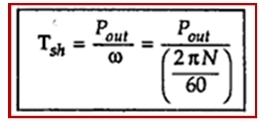
Key Point : The torque produced by rotor is gross mechanical torque and due to mechanical losses entire torque can not be available to drive load. The load torque is net output torque called shaft torque or useful torque and is denoted as Tsh. It is related to Pout as,

       and  Tsh < T due to mechanical losses.
1.1 Derivation of k in Torque Equation
We have seen earlier that
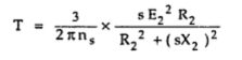
                       T = (k s E22 R2)/(R22 +(s X2)2)  
      and it mentioned that k = 3/(2π ns) . Let us see its proof.
       The rotor copper losses can be expressed as,
                      Pc = 3 x I2r2  x R2
       but I2r = (s E2)/√(R22 +(s X2)2), hence substituting above

      Now as per    P2 : Pc : Pm   is    1 : s : 1-s ,
                      Pc/P= s/(1-s)
      Now         P= T x ω
                             = T x (2πN/60)

       Now N = Ns (1-s) from definition of slip, substituting in above,

      but                 Ns/60 = ns in r.p.m.
      So substituting in the above equation,


Power Flow in an Induction Motor

Induction motor converts an electrical power supplies to it into mechanical power. The various stages in this conversion is called power flow in an inductor motor.
       The three phase supply given to the stator is the net electrical input to the motor. If motor power factor is cos Φ and VL, IL are line values of supply voltage and current drawn, then net electrical supplied to the motor can be calculated as,

       This is nothing but the stator input.
       The part of this power is utilised to supply the losses in the stator which are stator core as well as copper losses.
       The remaining power is delivered to the rotor magnetically through the air gap with the help of rotating magnetic field. This is called rotor input denoted as P2.

      The rotor is not able to convert its entire input to the mechanical as it has to supply rotor losses. The rotor losses are dominantly copper losses as rotor iron losses are very small and hence generally neglected. So rotor losses are rotor copper losses denoted as Pc.

       where     I2r = Rotor current per phase in running condition
                     R= Rotor resistance per phase.
       After supplying these losses, the remaining part of P2 is converted into mechanical which is called gross mechanical power developed by the motor denoted as Pm.

       Now this power, motor tries to deliver to the load connected to the shaft. But during this mechanical transmission, part of Pm is utilised to provide mechanical losses like friction and windage.
       And finally the power is available to the load at the shaft. This is called net output of the motor denoted as Pout. This is also called shaft power.

       The rating of the motor is specified in terms of value of Pout when load condition is full load condition.
       The above stages can be shown diagrammatically called power flow diagram of an induction motor.
       This is shown in the Fig.1.
Fig. 1 Power flow diagram

       From the power flow diagram we can define,


                                                         =  Pm / P2

Losses in Induction Motor

The various power losses in an induction motor can be classified as,
i) Constant losses
ii) Variable losses
i) Constant losses : 
      These can be further classified as core losses and mechanical losses.
      Core losses occur in stator core and rotor core. These are also called iron losses. These losses include eddy current losses and hysteresis losses. The eddy current losses are minimised by using laminated construction while hysteresis losses are minimised by selecting high grade silicon steel as the material for stator and rotor.
      The iron losses depends on the frequency. The stator frequency is always supply frequency hence stator iron losses are dominate. As against this in rotor circuit, the frequency is very small which is slip times the supply frequency. Hence rotor iron losses are very small and hence generally neglected, in the running condition.
      The mechanical losses include frictional losses at the bearings and windings losses. The friction changes with speed but practically the drop in speed is very small hence these losses are assumed to be the part of constant losses.
ii) Variable losses : 
      This include the copper losses in stator and rotor winding due to current flowing in the winding. As current changes as load changes as load changes, these losses are said to be variable losses.
       Generally stator iron losses are combined with stator copper losses at a particular load to specify total stator losses at particular load condition.
      Rotor copper loss = 3 I2r2 R2                        ......Analysed separately
where                    I2r  = Rotor current per phase at a particular load
                             R2  = Rotor resistance per phase

Sunday, 15 March 2015

Effect of Change in Rotor Resistance on Torque

It is shown that in slip ring induction motor, externally resistance can be added in the rotor. Let us see the effect of change in rotor resistance on the torque produced.
      Let                                   R2 = Rotor resistance per phase
      Corresponding torque,      T α  (s E22 R2)/√(R22 +(s X2)2
      Now externally resistance is added in each phase of rotor through slip rings.
      Let        R2' = New rotor resistance per phase
      Corresponding torque        T' α  (s E22 R2' )/√(R2'2 +(s X2)2
      Similarly the starting torque at s = 1 for R2 and R2' can be written as
                                                  Tst   α  (E22 R2 )/√(R22 +(X2)2
      and                                       T'st   α  (E22 R'2 )/√(R'22 +(X2)2
Maximum torque                          Tm α  (E22)/(2X2)
Key Point : It can be observed that Tm is independent of R2 hence whatever may be the rotor resistance, maximum torque produced never change but the slip and speed at which it occurs depends on R2.
      For R2,                                    sm = R2/X2            where Tm occurs
      For R2',                                    sm' = R2'/X2'          where same Tm occurs
      As R2' > R2, the slip sm' > sm. Due to this, we get a new torque-slip characteristics for rotor resistance . This new characteristics is parallel to the characteristics for with same but Tm occurring at sm'. The effect of change in rotor resistance on torque-slip characteristics shown in the Fig. 1.
      It can be seen that the starting torque T'st for R2' is more than Tst for R2. Thus by changing rotor resistance the starting torque can be controlled.
       If now resistance is further added to rotor to get resistance as R2' and so on, it can be seen that  Tm remains same but slip at which it occurs increases to sm' and so on. Similarly starting torque also increases to T'st and so on.
Fig.  1  Effect of rotor resistance on torque-slip curves

       If maximum torque Tm is required at start then sm = 1 as at start slip is always unity, so
                                   sm = R2/X2 = 1
                                    R2 = X2              Condition for getting   Tst = Tm
Key Point : Thus by adding external resistance to rotor till it becomes equal to X2, the maximum torque can be achieved at start.
       It is represented by point A in the Fig. 1.
       If such high resistance is kept permanently in the circuit, there will be large copper losses (I2 R)  and hence efficiency of the motor will be very poor. Hence such added resistance is cut-off gradually and finally removed from the rotor circuit, in the normal running condition of the motor. So this method is used in practice to achieve higher starting torque hence resistance in rotor is added only at start.
       Thus good performance at start and in the running condition is ensured.
Key Point : This is possible only in case of slip type of induction motor as in squirrel cage due to short circuited rotor, extra rotor resistance can not be added.
Example : Rotor resistance and standstill reactance per phase of a 3 phase induction motor are 0.04 Ω and 0.2 Ω respectively. What should be the external resistance required at start in rotor circuit to obtain.
i) maximum torque at start  ii) 50% of maximum torque at start.
Solution :
      R2 = 0.04 Ω,      X2 = 0.2 Ω
i)    For Tm = Tst ,     sm = R2'/X2 = 1
...              R2' = X2 = 0.2
      Let Rex = external resistance required in rotor.
                  R2' = R2 + Rex
...                Rex = R2' - R2 = 0.2 - 0.04 = 0.16 Ω per phase
ii)     For       Tst = 0.5 Tm,
      Now       Tm= (k E22)/(2 X2) and
                     Tst = (k E22 R2)/(R22 + X22)
       But at start, external resistance Rex is added. So new value of rotor resistance is say R2'.
                     R2' = R2 + Rex
...                  Tst =  (k  E22 R2')/(R2'2 + X22)   with added resistance
      but          Tst = 0.5Tm required.
      Substituting expressions of Tst and Tm, we get
                     (k  E22 R2')/(R2'2 + X22) = 0.5 (k E22)/ (2X2)
...                   4 R2' X2= (R2'2 + X22)
...                   (R2'2) - 4 x 0.2 x R2' + 0.22 = 0
...                    (R2'2) - 0.8 R2' + 0.04 = 0
...                    R2' = {0.8 + √(0.82 - 4 x 0.04)}/2
...                    R2' = 0.0535 , 0.7464 Ω
       But R2' can not greater than X2 hence,
                        R2' = 0.0535 = R2 + Rex
...                      0.0535 = 0.04 + Rex
...                      Rex = 0.0135 Ω per phase
       This is much resistance is required in the rotor externally to obtain  Tst = 0.5 Tm.

Speed Torque Characteristics in three phase induction motor

Uptill now, we have seen torque - slip characteristics of an induction motor. To compare the performance of induction motor with d.c. shunt and series motors, it is possible to plot speed-torque curve of an induction motor.
       At N = Ts, the motor stops as it can not produce any torque, as induction motor can not rotate at synchronous motor.
      At N = 0, the starting condition, motor produces a torque called starting torque.
Fig. 1   Speed Torque characteristics

       For low slip region, i.e. speeds near the region is stable and the characteristics is straight in nature. Fall in speed from no load to full load is about 4 to 6 %. The characteristics is shown in the Fig.1. It can be seen from that the figure that for the stable region of operation, the characteristics is similar to that of d.c. shunt motor. Due to this, three phase induction motor is practically said to be 'constant speed' motor as drop in speed from no load to full load is not significant. The unstable region of operation is shown dotted in the Fig.1.

Torque Ratios

The performance of the motor is sometimes expressed in terms of comparison of various torques such as full load torque, starting torque and maximum torque. The comparison is obtained by finding out ratios of these torques.
1.1 Full load and Maximum Torque Ratio
In general,        Tα (s E22 R2)/(R22 +(s X2)2)  
Let                     s= Full load slip
...                       TF.L. α (s E22 R2)/(R22 +(s X2)2)  
and                    sm = Slip for maximum torque T
...                       Tα (s E22 R2)/(R22 +(s X2)2)

       Dividing both numerator and denominator by X22 we get,
But                       R2/X2 = s
                            TF.L./T = (s x 2 sm2)/(sm x (sm2+ sf2))
                             TF.L./Tm   = (2 s sm)/(sm2 + sf2)
1.1 Starting Torque and Maximum Torque Ratio
       Against starting with torque equation as,
                           T α  (s E22 R2)/(R22 +(s X2)2)  
Now for Tst,        s =1
                           Tst  α   (E22 R2)/(R22 +( X2)2)
While for Tm,       s = sm
 
       Dividing both numerator and denominator by X22 we get,
      Substituting             R2/X2 = sm
 
       Infact using the same method, ratio of any two torques at two different slip values can be obtained.
       Sometimes using the relation, R2 = a X2 the torque ratios are expressed interms of constant a as,
                            TF.L./T = (a sf )/(a2+ sf2)
and                       Tst/T= 2 a/ (1 + a2)
where                    a = R2/X2 = sm
Example 1 : A 24 pole, 50 Hz, star connected induction motor has rotor resistance of 0.016 Ω per phase and rotor reactance of 0.265 Ω per phase at standstill. It is achieving its full load torque at a speed of 247 r.p.m. Calculate the ratio of 
i) Full load torque to maximum torque   ii) starting torque to maximum torque
Solution : Given values are,
   P = 24,   f = 50 Hz,       R2 = 0.016 Ω,   X2 = 0.265 Ω,     N = 247 r.p.m.
               N= 120f / P = (120x50)/24 = 250 r.p.m.
                s= (N- N)/N = (250-247)/250 = 0.012 = Full load slip
                 sm = R2/X2 = 0.016/0.265 = 0.06037
i)              TF.L./T= (2 sm sf )/(sm2+ sf2) = (2 x 0.06037 x 0.012)/(0.060372 + 0.0122)
ii)              Tst/T = (2 sm )/(1 + sm2) = (2 x 0.06037)/(1 + 0.060372) = 0.1203

Torque-Slip Characteristics in three phase induction motor

As the induction motor is located from no load to full load, its speed decreases hence slip increases. Due to the increased. load, motor has to produce more torque to satisfy load demand. The torque ultimately depends on slip as explained earlier. The behaviour of motor can be easily judged by sketching a curve obtained by plotting torque produced against slip of induction motor. The curve obtained by plotting torque against slip from s = 1 (at start) to s = 0 (at synchronous speed) is called torque-slip characteristics of the induction motor. It is very interesting to study the nature of torque-slip characteristics.
       We have seen that for a constant supply voltage,  E2 is also constant. So we can write torque equations as,

       Now to judge the nature of torque-slip characteristics let us divide the slip range (s = 0 to s = 1) into two parts and analyse them independently.

i) Low slip region :
       In low slip region, 's' is very very small. Due to this, the term (s X2)2 is so small as compared to R22 that it can be neglected.

       Hence in low slip region torque is directly proportional to slip. So as load increases, speed decreases, increasing the slip. This increases the torque which satisfies the load demand.
       Hence the graph is straight line in nature.
       At N = Ns , s = 0 hence T = 0. As no torque is generated at N = Ns, motor stops if it tries to achieve the synchronous speed. Torque increases linearly in this region, of low slip values.
ii) High slip region : 
       In this region, slip is high i.e. slip value is approaching to 1. Here it can be assumed that the term R22 is very very small as compared to (s X2)2. Hence neglecting from the denominator, we get

       So in high slip region torque is inversely proportional to the slip. Hence its nature is like rectangular hyperbola.
       Now when load increases, load demand increases but speed decreases. As speed decreases, slip increases. In high slip region as T α1/s, torque decreases as slip increases.
       But torque must increases to satisfy the load demand. As torque decreases, due to extra loading effect, speed further decreases and slip further increases. Again torque decreases as T  α1/s hence same load acts as an extra load due to reduction in torque produced. Hence speed further drops. Eventually motor comes to standstill condition. The motor can not continue to rotate at any point in this high slip region. Hence this region is called unstable region of operation.
       So torque - slip characteristics has two parts,
1. Straight line called stable region of operation
2. Rectangular hyperbola called unstable region of operation.
       Now the obvious question is upto which value of slip, torque - slip characteristics represents stable operation ?
       In low slip region, as load increases, slip increases and torque also increases linearly. Every motor has its own limit to produce a torque. The maximum torque, the  motor can produces as load increases is Tm which occurs at s = sm. So linear behaviour continues till s = sm.
       If load is increased beyond this limit, motor slip acts dominantly pushing motor into high slip region. Due to unstable conditions, motor comes to standstill condition at such a load. Hence i.e. maximum torque which motor can produce is also called breakdown torque or pull out torque. So range s = 0 to s = sm is called low slip region, known as stable region of operation. Motor always operates at a point in this region. And range s = sm to s = 1 is called high slip region which is rectangular hyperbola, called unstable region of operation. Motor can not continue to rotate at any point in this region.
       At s = 1, N = 0 i.e. start, motor produces a torque called starting torque denoted as Tst.
       The entire torque - slip characteristics is shown in the Fig. 1.
Fig. 1  Torque speed characteristics

1.1 Full load torque
      When the load on the motor increases, the torque produced increases as speed decreases and slip increases. The increases torque demand is satisfied by drawing motor current from the supply.
       The load which motor can drive safely while operating continuously and due to such load, the current drawn is also within safe limits is called full load condition of motor. When current increases, due to heat produced the temperature rise. The safe limit of current is that which when drawn for continuous operation of motor, produces a temperature rise well within the limits. Such a full load point is shown on the torque-slip characteristics torque as TF.L.
       The interesting thing is that the load on the motor can be increased beyond point C  till maximum torque condition. But due to high current and hence high temperature rise there is possibility of damage of winding insulation, if motor is operated for longer time duration in this region i.e. from point C  to B. But motor can be used to drive loads more than full load, producing torque upto maximum torque for short duration of time. Generally full load torque is less than the maximum torque.
        So region OC  upto full load condition allow motor operation continuously and safely from the temperature point pf view. While region CB  is possible to achieve in practice but only for short duration of time and not for continuous operation of motor. This is the difference between full load torque and the maximum or breakdown torque. The breakdown torque is also called stalling torque.
1.2 Generating and Braking Region
       When the slip lies in the region 0 and 1 i.e. when 0 ≤s ≤1, the machine runs as a motor which is the normal operation. The rotation of rotor is in the direction of rotating field which is developed by stator currents. In this region it takes electrical power from supply lines and supplies mechanical power output. The rotor speed and corresponding torque are in same direction.
      When the slip is greater than 1, the machine works in the braking mode. The motor is rotated in opposite direction to that of rotating field. In practice two of the stator terminals are interchanged which changes the phase sequence which in turn reverses the direction of rotation of magnetic field. The motor comes to quick stop under the influence of counter torque which produces braking action. This method by which the motor comes to rest is known as plugging. Only care is taken that the stator must be disconnected from the supply to avoid the rotor to rotate in other direction
       To run the induction machine as a generator, its slip must be less than zero i.e. negative. The negative slip indicates that the rotor is running at a speed above the synchronous speed. When running as a generator it takes mechanical energy and supplies electrical energy from the stator.
      Thus the negative slip, generation action takes place and nature of torque - slip characteristics reverses in this generating region.
      The Fig.2 shows the complete torque - slip characteristics showing motoring, generating and the braking region.
Fig. 2  Regions of torque - slip characteristics