Saturday 19 December 2015

Electrical Machine Interview Question And Answer

[1] Define the term synchronous speed [Dec-2003]
For synchronous machines there exists a fixed relationship between number of poles P, frequency (f) and the speed of the machine. The speed of the synchronous machine for the given number of poles and the rated frequency is called the synchronous speed mentioned as NS.

[2] Write an expression for synchronous speed (Dec-2004)
An expression for synchronous speed is NS = 120f/P.
Where
f = frequency
P = No of poles of the machine.

[3] What does speed voltage mean? (Dec-2007)
When the magnetic flux is constant as well as stationary and the coil rotates to cut the flux then EMF gets induced due to relative speed between flux and coil. This EMF is called speed EMF, rotational EMF or dynamically induced EMF.

[4] Mention the factors on which hysteresis loss depends (Dec-2008)
The hysteresis loss is directly proportional to the area under the hysteresis curve ie area of the hysteresis loop.
It is directly proportional to frequency ie number of cycles of magnetization per second.
It is directly proportional to volume of the material.

[5] Distinguish between statically induced and dynamically induced EMF (Dec - 2010, 2011, 2009)
How is EMF induced dynamically ( May-2010)
An induced EMF which is due to physical movement of coil, conductor with respect to flux or movement of magnet with respect to stationary coil, conductor is called dynamically induced EMF or motional induced EMF.
The change in flux lines with respect to coil can be achieved without physically moving the coil or the magnet. Such induced emf in a coil which is without physical movement of coil or a magnet is called statically induced EMF.

[6] Define torque (May-2010)
A turning or a twisting force about an axis is called as torque.

[8] What are the three types of basic rotating electric machines? (May-2011)
DC machines
Induction Machines
Synchronous Machines

[9] What are the causes of core loss? what are the components of core loss?
When a core is subjected to an alternating flux then it undergoes the cycles of magnetisation and demagnetisation. This produces hysteresis effect which causes hysteresis loss in the core.
Similarly core is under the influence of the changing flux and under such condition according to the Faraday's law of electromagnetic induction, EMF gets induced in the core. Such currents in the core which are due to induced emf in the core are called as eddy current loss. Thus eddy current and hysteresis are the two components of the core loss.

Tuesday 15 December 2015

Transformer Interview Questions With Answer

 Hello Friends. How are you ?

  We shared a lot of interview questions on electrical machines, power system and power electronics. Today we are sharing interview questions on transformer. These transformer interview questions is collected from various sources. lets start transformer interview questions with answer.

Q.1. How is magnetic leakage reduced to a minimum in commerical transformers ?
Ans.By interleaving the primary and secondary windings.

Q.2. Mention the factors on which hysteresis loss depends ?
Ans.(i) Quality and amount of iron in the core
       (ii) Flux density and
       (iii) Frequency.
Must Read :
  1.  Electrical Engineering Project Ideas
  2. Construction Of DC Machine
Q.3. How can eddy current loss be minimised ?
Ans.By laminating the core.

Q.4. In practice, what determines the thickness of the laminae or stampings ?
Ans.Frequency.

Q.5. Does the transformer draw any current when its secondary is open ?
Ans.Yes, no-load primary current.

Q.6. Why ?
Ans.For supplying no-load iron and copper losses in primary.

Q.7. Is Cu loss affected by power factor ?
Ans.Yes, Cu loss varies inversely with power factor.

Q.8. Why ?
Ans.Cu loss depends on current in the primary and secondary windings. It is well-known that current required is higher when power factor is lower.

Q.9. What effects are produced by change in voltage ?
Ans.1. Iron loss.........varies approximately as V2.
       2. Cu loss.........it also varies as V2 but decreases with an increase in voltage if constant kVA output is assumed
       3. Efficiency.........for distribution transformers, efficiency at fractional loads decreases with increase in voltage while at full load or overload it increases with increase in voltage and viceversa.

       4. Regulation.........it varies as V2  but decreases with increase in voltage if constant kVA output is assumed.
     5. Heating.........for constant kVA output, iron temperatures increase whereas Cu temperatures decrease with increase in voltages and vice-versa
.
Q. 10.How does change in frequency affect the operation of a given transformer ?
Ans. 1. Iron loss .........increases with a decrease in frequency. A 60-Hz transformer will have nearly 11%      higher losses when worked on 50Hz instead of 60 Hz. However, when a 25-Hz transformer is worked on 60 Hz, iron losses are reduced by 25%.

2. Cu loss.........in distribution transformers, it is independent of frequecy.
3. Efficiency.........since Cu loss is unaffected by change in frequency, a given transformer efficiency is less at a lower frequency than at a higher one.
4. Regulation.........regulation at unity power factor is not affected because IR drop is independent of frequency. Since reactive drop is affected, regulation at low power factors decreases with a decrease in frequency and vice-versa.

For example, the regulation of a 25-Hz transformer when operated at 50-Hz and low power factor is much poorer.

5. Heating.........since total loss is greater at a lower frequency, the temperature is increased with decrease in frequency.

If you face any problem then comment below

Searches related to Transformer Interview Questions With Answer

transformer interview questions and answers pdf

cognos transformer interview questions and answers

electrical interview questions and answers on transformers

interview questions on transformer protection

interview questions on transformer stage in datastage


Saturday 29 August 2015

Electrical Engineering Project Ideas For Final Year

  1. UPFC - Unified Power Factor Control.
  2. Construction of Central Control Unit for Irrigation water pumps.
  3. Cost effective method to control entire villager’s water pumps with user level authentication. Illiterate’s friendly system.
  4. Centralized energy meter for display distance at 30meters - Avoiding tampering of electrical energy meter in houses
  5. Embedded System Integrated Into a Wireless Sensor Network for Online DynamicTorque and Efficiency Monitoring in Induction Motors
  6.  Design and Implementation of Intelligent Energy Distribution Management with Photovoltaic System
  7. Sensor Network Based Oil well Health Monitoring and Intelligent Control
  8. . Solar induction motor driver. 
  9. Speed control of universal motor with automated ON load and OFF load sensing
  10. . Solar tracking system with automated water pump controlling
  11.  Touch screen based AC motor speed Monitoring and control system
  12.  Touch screen based wireless AC motor speed Monitoring and control system
  13.  Intelligent Transformer Isolation system using PC
  14. Real time Atomization of Indian Agricultural system.
  15. Automated Solar Street lighting system using LED’s
  16. GSM based Energy meter with tampering alert
  17. Event driven automation with Android backup control
  18. Transformer over load alert through voice announcement.
  19. Wireless Power Factor monitoring and controlling through PC
  20. Protection of power transformer using microcontroller-based relay
  21. Industrial parameters monitoring and crane controlling using Zigbee
  22. Transformer load sharing with SMS alerting.
  23. Multi zone temperature monitoring with voice announcement system.
  24. Maximum demand controller & fault alerting for industries.
  25. speed control of exhaust fan using RF remote.
  26. Solar Tracker Robot using Microcontroller
  27. Design and Implementation of intelligent Urban Irrigation System
  28. Remote Controlled Screw Jack
  29. Microcontroller based smart charge controller for standalone solar photovoltaic power systems.
  30. GPRS based single phase fault monitoring and SMS alert 
  31. Design and construction of parabolic solar reflectors
  32. Servo Motor Control using mobile phone.
  33. Wireless power theft monitoring with automatic circuit breaker system and indication at local substations
  34. Energy Tapping Identifier through Wireless Data Acquisition System
  35. Foot step power generation system.
  36. Multi channel voltage scanner
  37. Controlling of exhaust fan based on Smoke and Gas intensity in industries.
  38. Four channel fault annunciation for industries.
  39. Feeder Protection From Over Load.
  40. Temp based speed control of exhaust fan using TRIAC.
  41. Petrochemical Level Indicator and Controller for Automation of cotton purification process in spinning mills.
  42. Autonomous energy meter with auto announcement system
  43. Solar based self powered high efficient Line following robot with obstacle avoidance
  44. Zigbee based power management system
  45. Speech recognition based Wheel chair with elevated features
  46. Water level indicator on LCD
  47. DTMF 3-phase irrigation Control with Feedback
  48. I-Button & keypad based DC motor door lock system

Searches related to electrical engineering projects


electrical engineering projects for college students

electrical engineering project ideas

electrical engineering projects for high school students

electrical engineering projects for beginners


electrical engineering projects for kids

electrical engineering science fair projects

computer engineering projects

electrical engineering projects list

Sunday 19 July 2015

Basic MCQ Interview Questions On Alternator

 Hello Reader. Today we collected basic mcq types questions of alternator.

Ques.[1] At lagging loads, armature reaction in an alternator is
(a) cross-magnetizing
(b) demagnetizing
(c) non-effective
(d) magnetizing.
Answer : D

Ques.[2] At leading p.f., the armature flux in an alternator....... the rotor flux.
(a) opposes
(b) aids
(c) distorts
(d) does not affect.
Answer : B

Ques.[3] The voltage regulation of an alternator having 0.75 leading p.f. load, no-load induced e.m.f.of 2400V and rated terminal voltage of 3000V is............... percent.
(a)20
(b)−20
(c) 150
(d)−26.7
Answer : B

Ques.[4] If, in a 3-phase alternator, a field current of 50A produces a full-load armature current of 200 A on short-circuit and 1730 V on open circuit, then its synchronous impedance is ....... ohm.
(a) 8.66
(b)4
(c)5
(d) 34.6
Answer : C

Ques.[5] The power factor of an alternator is determined by its
(a) speed
(b) load
(c) excitation
(d) prime mover.
Answer : B

Must Read: What is thermal Power Plant

Ques.[6] For proper parallel operation, a.c. polyphase alternators must have the same
(a) speed
(b) voltage rating
(c) kVA rating
(d) excitation.
Answer : B

Ques.[7] Of the following conditions, the one which does not have to be met by alternators working in parallel is
(a) terminal voltage of each machine must be the same
(b) the machines must have the same phase rotation
(c) the machines must operate at the same frequency
(d) the machines must have equal ratings.
Answer : D

Ques.[8] After wiring up two 3-φ alternators, you checked their frequency and voltage and found them to be equal. Before connecting them in parallel, you would
(a) check turbine speed
(b) check phase rotation
(c) lubricate everything
(d) check steam pressure.
Answer : B

Ques.[9] Zero power factor method of an alternator is used to find its
(a) efficiency
(b) voltage regulation
(c) armature resistance
(d) synchronous impedance.
Answer : B

Ques.[10] Some engineers prefer `lamps bright' synchronization to ‘lamps dark’ synchronization because(a) brightness of lamps can be judged easily
(b) it gives sharper and more accurate synchronization
(c) flicker is more pronounced
(d) it can be performed quickly.
Answer : B

Ques.[11] It is never advisable to connect a stationary alternator to live bus-bars because it

(a) is likely to run as synchronous motor
(b) will get short-circuited
(c) will decrease bus-bar voltage though momentarily
(d) will disturb generated e.m.fs. of other alternators connected in parallel
Answer : B

Ques.[12] Two identical alternators are running in parallel and carry equal loads. If excitation of one alternator is increased without changing its steam supply, then
(a) it will keep supplying almost the same load
(b) kVAR supplied by it would decrease
(c) its p.f. will increase
(d) kVA supplied by it would decrease.
Answer : A

Ques.[13] Keeping its excitation constant, if steam supply of an alternator running in parallel with another identical alternator is increased, then
(a) it would over-run the other alternator
(b) its rotor will fall back in phase with respect to the other machine
(c) it will supply greater portion of the load
(d) its power factor would be decreased.
Answer : C

Ques.[14] The load sharing between two steam-driven alternators operating in parallel may be adjusted by varying the
(a) field strengths of the alternators
(b) power factors of the alternators
(c) steam supply to their prime movers
(d) speed of the alternators.
Answer : C

Ques.[15] Squirrel-cage bars placed in the rotor pole faces of an alternator help reduce hunting
(a) above synchronous speed only
(b) below synchronous speed only
(c) above and below synchronous speeds both
(d) none of the above. (Elect. Machines, A.M.I.E. Sec. B, 1993)
Answer : C

Ques.[16] For a machine on infinite bus active power can be varied by
(a) changing field excitation
(b) changing of prime cover speed
(c) both (a) and (b) above
(d) none of the above .
Answer : B

Q.[17] The frequency of voltage generated by an alternator having 4-poles and rotating at 1800 r.p.m.is .......hertz.
(a)60
(b) 7200
(c) 120
(d) 450.
Answer : A

Q.[18] A 50-Hz alternator will run at the greatest possible speed if it is wound for ....... poles.
(a)8
(b)6
(c)4
(d)2.
Answer : D

Q.[19] The main disadvantage of using short-pitch winding in alternators is that it
(a) reduces harmonics in the generated voltage
(b) reduces the total voltage around the armature coils
(c) produces asymmetry in the three phase windings
(d) increases Cu of end connections.
Answer : B

Q.[20] Three-phase alternators are invariably Y-connected because
(a) magnetic losses are minimized
(b) less turns of wire are required
(c) smaller conductors can be used
(d) higher terminal voltage is obtained.
Answer : D

Q.[21] The winding of a 4-pole alternator having 36 slots and a coil span of 1 to 8 is short-pitched by ....... degrees.
(a) 140
(b)80
(c)20
(d) 40.
Answer : D

Q.[22] If an alternator winding has a fractional pitch of 5/6, the coil span is ....... degrees.
(a) 300
(b) 150
(c)30
(d) 60.
Answer : B

Q.[23] The harmonic which would be totally eliminated from the alternator e.m.f. using a fractional pitch of 4/5 is
(a) 3rd
(b)7th
(c) 5th
(d) 9th.
Answer : C

Q.[24] For eliminating 7th harmonic from the e.m.f. wave of an alternator, the fractional-pitch must be
(a) 2/3
(b)5/6
(c) 7/8
(d) 6/7.
Answer : D

Q.[25] If, in an alternator, chording angle for fundamental flux wave is α, its value for 5th harmonic is
(a)5α
(b)α/5
(c)25α
(d)α/25.
Answer : A

Q.[26] Regarding distribution factor of an armature winding of an alternator which statement is false?(a) it decreases as the distribution of coils (slots/pole) increases
(b) higher its value, higher the induced e.m.f.per phase
(c) it is not affected by the type of winding either lap, or wave
(d) it is not affected by the number of turns per coil.
Answer : B

Q.[27] When speed of an alternator is changed from 3600 r.p.m. to 1800 r.p.m., the generated e.m.f./phases will become
(a) one-half
(b) twice
(c) four times
(d) one-fourth.
Answer : A

Q.[28] The magnitude of the three voltage drops in an alternator due to armature resistance, leakage reactance and armature reaction is solely determined by
(a) load current, Ia
(b) p.f. of the load
(c) whether it is a lagging or leading p.f. load
(d) field construction of the alternator.
Answer : A

Q.[29]Armature reaction in an alternator primarily affects
(a) rotor speed
(b) terminal voltage per phase
(c) frequency of armature current
(d) generated voltage per phase.
Answer : D

Q.[30] Under no-load condition, power drawn by the prime mover of an alternator goes to
(a) produce induced e.m.f. in armature winding
(b) meet no-load losses
(c) produce power in the armature
(d) meet Cu losses both in armature and rotor windings.
Answer : B

Q.[31] As load p.f. of an alternator becomes more leading, the value of generated voltage required to give rated terminal voltage
(a) increases
(b) remains unchanged
(c) decreases
(d) varies with rotor speed.
Answer : C


Q.[32] With a load p.f. of unity, the effect of armature reaction on the main-field flux of an alternator is
(a) distortional
(b) magnetizing
(c) demagnetizing
(d) nominal
Answer : A
If you have any problem then comment below.

Searches related to Basic MCQ Interview Questions On Alternator

electrical machines objective questions and answers pdf
electrical machines objective questions pdf download
mcq on alternator with answers
power factor of alternator at no load
objective questions on synchronous machines pdf
open wire test is used for?
synchronous machines questions and answers
synchronous machines objective questions with answers

Searches related to alternator working

alternator working principle pdf
alternator construction
alternator working animation
alternator working video
alternator pdf
alternator generator
car alternator working
brushless alternator working principle

Saturday 6 June 2015

Construction of a DC Machine And working of dc motor

As stated earlier, whether a machine is d.c. generator or a motor the construction basically remains the same as shown in the Fig. 1.
Fig.1 A cross section of typical d.c. machine
It consists of the following parts :
1.1 Yoke
a) Functions :
  1. It serves the purpose of outermost cover of the d.c. machine. So that the insulating materials get protected from harmful atmospheric elements like moisture, dust and various gases like SO2, acidic fumes etc.
  2. It provides mechanical support to the poles.
  3. It forms a part of the magnetic circuit. It provides a path of low reluctance for magnetic flux. The low reluctance path is important to avoid wastage of power to provide same flux. Large current and hence the power is necessary if the path has high reluctance, to produce the same flux.
b) Choice of Material : To provide low reluctance path, it must be made up of some magnetic material. It is prepared by using cast iron because it is cheapest. For large machines rolled steel, cast steel, silicon steel is used which provides high permeability i.e. low reluctance and gives good mechanical strength.
1.2 Poles
       Each pole is divided into two parts namely, I) Pole core and II) Pole shoe.
       This is shown in the Fig. 2.
Fig. 2 Pole Structure
a) Functions of pole core and pole shoe :
  1. Pole core basically carries a field winding which is necessary to produce the flux.
  2. It directs the flux produced through air gap to armature core, to the next pole.
  3. Pole shoe enlarges the area of armature core to come across the flux, which is necessary to produce larger induced e.m.f. To achieve this, pole shoe has been given a particular shape. 
b) Choice of Material : It is made up of magnetic material like cast iron or cast steel. As it requires a definite shape and size, laminated construction is used. The laminations of required size and shape are stamped together to get a pole which is then bolted to the yoke.
1.3 Field Winding (F1-F2)
       The field winding is wound on the pole core with a definite direction.
a) Functions : To carry current due to which pole core, on which the field winding is placed behaves as an electromagnet, producing necessary flux.
       As it helps in producing the magnetic field i.e. exciting the pole as an electromagnet it is called Field winding or Exciting winding.
b) Choice of material : It has to carry current hence obviously made up of some conducting material. So aluminium or copper is the choice. But field coils are required to take any type of shape and bend about pole core and copper has good pliability i.e. it can bend easily. So copper is the proper choice.
Note : Field winding is divided into various coils called field coils. These are connected in series with each other and in such a direction around pole cores, such that alternate 'N' and 'S' poles are formed.
       By using right hand thumb rule for current carrying circular conductor, it can be easily determined that how a particular core is going to behave as 'N' or 'S' for a particular winding direction around it. The direction of winding and flux can be observed in the Fig 3. 
Fig. 3
1.4 Armature 
       It is further divided into two parts namely,
I) Armature core and II) Armature winding
I) Armature core : Armature core is cylindrical in shape mounted on the shaft. It consists of slots on its periphery and the air ducts to permit the air flow through armature which serves cooling purpose.
a) Functions :
  1. Armature core provides house for armature winding i.e. armature conductors.
  2. To provide a path of low reluctance to the magnetic flux produced by the field winding.
b) Choice of Material : As it has to provide a low reluctance path to the flux, it is made up of magnetic material like cast iron or cast steel.
       It is made up of laminated construction to keep eddy current loss as low as possible. A single circular lamination used for the construction of the armature core is shown in the Fig. 4.
Fig. 4 Single Circular lamination of Armature core
II) Armature winding : Armature winding is nothing but the interconnection of the armature conductors, placed in the slots provided on the armature core periphery. When the armature is rotated, in case of generator, magnetic flux gets cut by armature conductors and e.m.f. gets induced in them.
a) Functions :
  1. Generation of e.m.f takes place in the armature winding in case of generators.
  2. To carry the current supplied in case of d.c. motors.
  3. To do the useful work in the external circuit. 
b) Choice of material : As armature winding carries entire current which depends on external load, it has to be made up of conducting material, which is copper.
       Armature winding is generally former wound. The conductors are placed in the armature slots which are lined with tough insulating material.
1.5 Commutator 
We have seen earlier that the basic nature of e.m.f. induced in the armature conductors is alternating. This needs rectification in case of d.c. generator, which is possible by a device called commutator.
a) Functions :
  1. To facilitate the collection of current from the armature conductors.
  2. To convert internally developed alternating e.m.f. to unidirectional (d.c.) e.m.f.
  3. To produce unidirectional torque in case of motors.
b) Choice of material : As it collects current from armature, it is also made up of copper segments.
       It is cylindrical in shape and is made up of wedge shaped segments of the hard drawn, high conductivity copper. These segments are insulated from each other by thin layer of mica. Each commutator segment is connected to the armature conductor by means of copper lug or strip. This connection is shown in the Fig. 5.
Fig. 5 Commutator
1.6 Brushes and Brush Gear
       Brushes are stationary and resting on the surface of the commutator.
a) Function : To collect current from commutator and make it available to the stationary external circuit.
b) Choice of material : Brushes are normally made up of soft material like carbon.
       Brushes are rectangular in shape. They are housed in brush holders, which are usually of box type. The brushes are made to press on the commutator surface by means of a spring, whose tension can be adjusted with the help of lever. A flexible copper conductor called pig tail is used to connect the brush to the external circuit. To avoid wear and tear of commutator, the brushes are made up of soft material like carbon.
1.7 Bearings 
       Ball-bearings are usually used as they are more reliable. For heavy duty machines, roller bearings are prederred.

Searches related to Construction of a DC Machine


construction of dc machine pdf

working principle of dc machine

basic construction of dc machines

commutation of dc generator


parts of dc machine

direct current machine

general principles of dc machines

principle operation of dc generator

Monday 18 May 2015

Gas Turbine Power Plant

Gas Turbine Power Plant

A generating station which employs gas turbine as the prime mover for the generation of electrical
energy is known as a gas turbine power plant

In a gas turbine power plant, air is used as the working fluid. The air is compressed by the compressor and is led to the combustion chamber where heat is added to air, thus raising its temperature. Heat is added to the compressed air either by burning fuel in the chamber or by the use of air heaters. The hot and high pressure air from the combustion chamber is then passed to the gas turbine where it expands and does the mechanical work. The gas turbine drives the alternator which converts mechanical energy into electrical energy.

It may be mentioned here that compressor, gas turbine and the alternator are mounted on the same shaft so that a part of mechanical power of the turbine can be utilised for the operation of the compressor. Gas turbine power plants are being used as standby plants for hydro-electric stations, as a starting plant for driving auxiliaries in power plants etc.

Advantages
(i) It is simple in design as compared to steam power station since no boilers and their auxiliaries are required.
(ii) It is much smaller in size as compared to steam power station of the same capacity. This is expected since gas turbine power plant does not require boiler, feed water arrangement etc.

(iii) The initial and operating costs are much lower than that of equivalent steam power station.
(iv) It requires comparatively less water as no condenser is used.
(v) The maintenance charges are quite small.
(vi) Gas turbines are much simpler in construction and operation than steam turbines.
(vii) It can be started quickly form cold conditions.
(viii) There are no standby losses. However, in a steam power station, these losses occur because boiler is kept in operation even when the steam turbine is supplying no load.

Disadvantages
(i) There is a problem for starting the unit. It is because before starting the turbine, the compressor has to be operated for which power is required from some external source. However, once the unit starts, the external power is not needed as the turbine itself supplies the necessary power to the compressor.
(ii) Since a greater part of power developed by the turbine is used in driving the compressor, the net output is low.
(iii) The overall efficiency of such plants is low (about 20%) because the exhaust gases from the turbine contain sufficient heat.
(iv) The temperature of combustion chamber is quite high (3000oF) so that its life is comparatively reduced.

Schematic Arrangement of Gas Turbine Power Plant

The schematic arrangement of a gas turbine power plant is shown in . The main components
of the plant are :
(i) Compressor (ii) Regenerator (iii)Combustion chamber (iv) Gas turbine (v) Alternator (vi) Starting motor

(i) Compressor.  The compressor used in the plant is generally of rotatory type. The air at atmospheric pressure is drawn by the compressor viathe filter which removes the dust from air. The rotatory blades of the compressor push the air between stationary blades to raise its pressure. Thus air at high pressure is available at the output of the compressor.

(ii) Regenerator. A regenerator is a device which recovers heat from the exhaust gases of the turbine. The exhaust is passed through the regenerator before wasting to atmosphere. A regenerator consists of a nest of tubes contained in a shell. The compressed air from the compressor passes through the tubes on its way to the combustion chamber. In this way, compressed air is heated by the hot exhaust gases.

(iii) Combustion chamber. The air at high pressure from the compressor is led to the combustion chamber viathe regenerator. In the combustion chamber, heat*is added to the air by burning oil. The oil is injected through the burner into the chamber at high pressure to ensure atomisation of oil and its thorough mixing with air. The result is that the chamber attains a very high temperature (about 3000oF). The combustion gases are suitably cooled to 1300o F to 1500o F and then delivered to the gas turbine.

(iv) Gas turbine. The products of combustion consisting of a mixture of gases at high temperature and pressure are passed to the gas turbine. These gases in passing over the turbine blades expand and thus do the mechanical work. The temperature of the exhaust gases from the turbine is about 900oF.

(v) Alternator. The gas turbine is coupled to the alternator. The alternator converts mechanical energy of the turbine into electrical energy. The output from the alternator is given to the bus-bars through transformer, circuit breakers and isolators.
(vi) Starting motor. Before starting the turbine, compressor has to be started. For this purpose, an electric motor is mounted on the same shaft as that of the turbine. The motor is energised by the batteries. Once the unit starts, a part of mechanical power of the turbine drives the compressor and there is no need of motor now.

Introduction To Nuclear Power Station

Nuclear Power Station


A generating station in which nuclear energy is converted into electrical energy is known as a nuclear power station.
In nuclear power station, heavy elements such as Uranium (U235) or Thorium (Th232) are subjected to nuclear fission.  in a special apparatus known as a reactor.The heat energy thus released is utilised in raising steam at high temperature and pressure. The steam runs the steam turbine which converts steam energy into mechanical energy. The turbine drives the alternator which converts mechanical energy into electrical energy.
The most important feature of a nuclear power station is that huge amount of electrical energy can be produced from a relatively small amount of nuclear fuel as compared to other conventional types of power stations. It has been found that complete fission of 1 kg of Uranium (U235) can produce as much energy as can be produced by the burning of 4,500 tons of high grade coal. Although the recovery of principal nuclear fuels (i.e., Uranium and Thorium) is difficult and expensive, yet the total energy content of the estimated world reserves of these fuels are considerably higher than those of conventional fuels, viz., coal, oil and gas.

At present, energy crisis is gripping us and, therefore, nuclear energy can be successfully employed for producing low cost electrical energy on a large scale to meet the growing commercial and industrial demands.

Advantages
(i) The amount of fuel required is quite small. Therefore, there is a considerable saving in the cost of fuel transportation.
(ii) A nuclear power plant requires less space as compared to any other type of the same size.
(iii) It has low running charges as a small amount of fuel is used for producing bulk electrical energy.
(iv) This type of plant is very economical for producing bulk electric power.
(v) It can be located near the load centres because it does not require large quantities of water and need not be near coal mines. Therefore, the cost of primary distribution is reduced.
(vi) There are large deposits of nuclear fuels available all over the world. Therefore, such plants can ensure continued supply of electrical energy for thousands of years.
(vii) It ensures reliability of operation.

Disadvantages
(i) The fuel used is expensive and is difficult to recover.
(ii) The capital cost on a nuclear plant is very high as compared to other types of plants.
(iii) The erection and commissioning of the plant requires greater technical know-how.
(iv) The fission by-products are generally radioactive and may cause a dangerous amount of radioactive pollution
(v) Maintenance charges are high due to lack of standardisation. Moreover, high salaries of specially trained personnel employed to handle the plant further raise the cost.
(vi) Nuclear power plants are not well suited for varying loads as the reactor does not respond to the load fluctuations efficiently.
(vii) The disposal of the by-products, which are radioactive, is a big problem. They have either to be disposed off in a deep trench or in a sea away from sea-shore.

Schematic Arrangement of Nuclear Power Station

The schematic arrangement of a nuclear power station is shown in Fig.. The whole arrangement can be divided into the following main stages :
(i) Nuclear reactor (ii) Heat exchanger (iii) Steam turbine (iv) Alternator.

(i) Nuclear reactor.  It is an apparatus in which nuclear fuel (U 235 ) is subjected to nuclear fission. It controls the chain reaction that starts once the fission is done. If the chain reaction is not controlled, the result will be an explosion due to the fast increase in the energy released.
A nuclear reactor is a cylindrical stout pressure vessel and houses fuel rods of Uranium, moderator and control rods . The fuel rods constitute the fission material and release huge amount of energy when bombarded with slow moving neutrons. The moderator consists of graphite rods which enclose the fuel rods. The moderator slows down the neutrons before they bombard the fuel rods. The control rods are of cadmium and are inserted into the reactor. Cadmium is strong neutron absorber and thus regulates the supply of neutrons for fission. When the control rods are pushed in deep enough, they absorb most of fission neutrons and hence few are available for chain reaction which, therefore, stops.

However, as they are being withdrawn, more and more of these fission neutrons cause fission and hence the intensityof chain reaction (or heat produced) is increased. Therefore, by pulling out the control rods, power of the nuclear reactor is increased, whereas by pushing them in, it is reduced. In actual practice, the lowering or raising of control rods is accomplished automatically according to the requirement of load. The heat produced in the reactor is removed by the coolant, generally a sodium metal. The coolant carries the heat to the heat exchanger

(ii) Heat exchanger. The coolant gives up heat to the heat exchanger which is utilised in raising the steam. After giving up heat, the coolant is again fed to the reactor

(iii) Steam turbine. The steam produced in the heat exchanger is led to the steam turbine through a valve. After doing a useful work in the turbine, the steam is exhausted to condenser. The condenser condenses the steam which is fed to the heat exchanger through feed water pump.

(iv) Alternator. The steam turbine drives the alternator which converts mechanical energy into electrical energy. The output from the alternator is delivered to the bus-bars through transformer, circuit breakers and isolators.

Selection of Site for Nuclear Power Station

The following points should be kept in view while selecting the site for a nuclear power station :

(i) Availability of water.  As sufficient water is required for cooling purposes, therefore, the plant site should be located where ample quantity of water is available, e.g., across a river or by sea-side.

(ii) Disposal of waste.  The waste produced by fission in a nuclear power station is generally radioactive which must be disposed off properly to avoid health hazards. The waste should either be buried in a deep trench or disposed off in sea quite away from the sea shore. Therefore, the site selected for such a plant should have adequate arrangement for the disposal of radioactive waste.

(iii) Distance from populated areas.  The site selected for a nuclear power station should be quite away from the populated areas as there is a danger of presence of radioactivity in the atmosphere near the plant. However, as a precautionary measure, a domeis used in the plant which does not allow the radioactivity to spread by wind or underground waterways.

(iv) Transportation facilities. The site selected for a nuclear power station should have adequate facilities in order to transport the heavy equipment during erection and to facilitate the movement of the workers employed in the plant. From the above mentioned factors it becomes apparent that ideal choice for a nuclear power station would be near sea or river and away from thickly populated areas.


What is Diesel Power Station

Diesel Power Station

A generating station in which diesel engine is used as the prime mover for the generation of electrical energy is known as diesel power station.

In a diesel power station, diesel engine is used as the prime mover. The diesel burns inside the engine and the products of this combustion act as the “working fluid” to produce mechanical energy. The diesel engine drives the alternator which converts mechanical energy into electrical energy. As the generation cost is considerable due to high price of diesel, therefore, such power stations are only used to produce small power.

Although steam power stations and hydro-electric plants are invariably used to generate bulk power at cheaper cost, yet diesel power stations are finding favour at places where demand of power is less, sufficient quantity of coal and water is not available and the transportation facilities are inadequate. These plants are also used as standby sets for continuity of supply to important points such as hospitals, radio stations, cinema houses and telephone exchanges.

Advantages
(i) The design and layout of the plant are quite simple.
(ii) It occupies less space as the number and size of the auxiliaries is small.
(iii) It can be located at any place.
(iv) It can be started quickly and can pick up load in a short time.
(v) There are no standby losses.
(vi) It requires less quantity of water for cooling.
(vii) The overall cost is much less than that of steam power station of the same capacity.
(viii) The thermal efficiency of the plant is higher than that of a steam power station.
(ix) It requires less operating staff.

Disadvantages
(i) The plant has high running charges as the fuel (i.e., diesel) used is costly.
(ii) The plant does not work satisfactorily under overload conditions for a longer period.
(iii)The plant can only generate small power.
(iv) The cost of lubrication is generally high.
(v) The maintenance charges are generally high.

Schematic Arrangement of Diesel Power Station

Fig. shows the schematic arrangement of a typical diesel power station. Apart from the dieselgenerator set, the plant has the following auxiliaries :
Diesel Power Station

(i) Fuel supply system. It consists of storage tank, strainers, fuel transfer pump and all day fuel tank. The fuel oil is supplied at the plant site by rail or road. This oil is stored in the storage tank. From the storage tank, oil is pumped to smaller all day tank at daily or short intervals. From this tank, fuel oil is passed through strainers to remove suspended impurities. The clean oil is injected into the engine by fuel injection pump.

(ii) Air intake system.  This system supplies necessary air to the engine for fuel combustion. It consists of pipes for the supply of fresh air to the engine manifold. Filters are provided to remove dust particles from air which may act as abrasive in the engine cylinder.

(iii) Exhaust system.  This system leads the engine exhaust gas outside the building and discharges it into atmosphere. A silencer is usually incorporated in the system to reduce the noise level.

(iv) Cooling system. The heat released by the burning of fuel in the engine cylinder is partially converted into work. The remainder part of the heat passes through the cylinder walls, piston, rings etc. and may cause damage to the system. In order to keep the temperature of the engine parts within the safe operating limits, cooling is provided. The cooling system consists of a water source, pump and cooling towers. The pump circulates water through cylinder and head jacket. The water takes away heat form the engine and itself becomes hot. The hot water is cooled by cooling towers and is recirculated for cooling.

(v) Lubricating system. This system minimises the wear of rubbing surfaces of the engine. It comprises of lubricating oil tank, pump, filter and oil cooler. The lubricating oil is drawn from the lubricating oil tank by the pump and is passed through filters to remove impurities. The clean lubricating oil is delivered to the points which require lubrication. The oil coolers incorporated in the system keep the temperature of the oil low.
(vi) Engine starting system.  This is an arrangement to rotate the engine initially, while starting, until firing starts and the unit runs with its own power. Small sets are started manually by handles but for larger units, compressed air is used for starting. In the latter case, air at high pressure is admitted to a few of the cylinders, making them to act as reciprocating air motors to turn over the engine shaft. The fuel is admitted to the remaining cylinders which makes the engine to start under its own power

Synchronous Generator Interview Questions

Q:Why syn. generators are used for the production of electricity?
A:synchronous machines have capability to work on different power factor(or say different imaginary power varying the field emf. Hence syn. generators are used for the production of electricity.

Q:What is the difference between synchronous generator & asynchronous generator?
A:In simple, synchronous generator supply's both active and reactive power but asynchronous generator(induction generator) supply's only active power and observe reactive power for magnetizing.This type of generators are used in windmills.

Q:1 ton is equal to how many watts?
A:1 ton = 12000 BTU/hr and to convert BTU/hr to horsepower, 12,000 * 0.0003929 = 4.715 hp therefore 1 ton = 4.715*.746 = 3.5 KW.

Q:Enlist types of dc generator?
A:D.C.Generators are classified into two types 1)separatly exicted d.c.generator 2)self exicted d.c.generator, which is further classified into;1)series 2)shunt and 3)compound(which is further classified into cumulative and differential).

Q:What is Automatic Voltage regulator(AVR)?
A:AVR is an abbreviation for Automatic Voltage Regulator.It is important part in Synchronous Generators, it controls theoutput voltage of the generator by controlling its excitation current. Thus it can control the output Reactive Power of the Generator.

Q:What is an exciter and how does it work?
A:There are two types of exciters, static exciter and rotory exciter.purpose of excitor is to supply the excitation dc voltage to the fixed poles of generator.Rotory excitor is an additional small generator mounted on the shaft of main generator. if it is dc generator, it will supply dc to the rotory poles through slip ring and brushes( conventional alternator). if it is an ac excitor, out put of ac excitor is rectified by rotating diodes and supply dc to main fixed poles.ac excitor is the ac generator whose field winding are stationary and armature rotates. initial voltage is built up by residual magnetism.It gives the starting torque to the generator. 

Q:Difference between a four point starter and three point starter?
A:The shunt connection in four point stater is provided separately form the line where as in three point stater it is connected with line which is the drawback in three point stater

Q:Why use the VCB at High Transmission System ? Why can't use ACB?
A:Actually the thing is vacuum has high arc queching property compare to air because in VCB ,the die electric strengths equal to 8 times of air . That y always vaccum used as inHT breaker and air used as in LT .
Q:What is the difference between surge arrestor and lightning arrestor?
A:LA is installed outside and the effect of lightning is grounded,where as surge arrestor installed inside panels comprising of resistors which consumes the energy and nullify the effect of surge.

Q:What will happen when power factor is leading in distribution of power?
A:If their is high power factor, i.e if the power factor is close to one:
1.losses in form of heat will be reduced,
2.cable becomes less bulky and easy to carry, and very cheap to afford, &
3. it also reduces over heating of tranformers.

Q:whats the one main difference between UPS & inverter ? And electrical engineering & electronics engineering ?
A:uninterrupt power supply is mainly use for short time . means according to ups VA it gives backup. ups is also two types : on line and offline . online ups having high volt and amp for long time backup with with high dc voltage.but ups start with 12v dc with 7 amp. but inverter is startwith 12v,24,dc to 36v dc and 120amp to 180amp battery with long time backup.


Q:What is 2 phase motor?
A:A two phase motor is a motor with the the starting winding and the running winding have a phase split. e.g;ac servo motor.where the auxiliary winding and the control winding have a phase split of 90 degree.

Q:Advantages of vvvf drives over non vvvf drives for EOT cranes?
A:1.smooth start and stop.
2.no jerking of load.
3.exact posiitoning
4.better protection for motor.
5.high/low speed selection.
6.reliability of break shoe.
7.programmable break control.
8.easy circutry
9.reduction in controls
10.increases motor life

Q:What is the significance of vector grouping in Power Transformers?
A:Every power transformer has a vector group listed by its manufacturer. Fundamentally it tells you the information about how the windings are connected (delta or wye) and the phace difference betweent the current and voltage. EG. DYN11 means Delta primary, Wye Secondry and the current is at 11 o clock reffered to the voltage.

Q:Which type of A.C motor is used in the fan (ceiling fan, exhaust fan, padestal fan, bracket fan etc) which are find in the houses ?
A:Its Single Phase induction motor which mostly squirrel cage rotor and are capacitor start capacitor run

Basic Electrical Engineering Interview Questions Part 1

Q:How tube light circuit is connected and how it works?
A:A choke is connected in one end of the tube light and a starter is in series with the circuit. When supply is provided ,the starter will interrupt the supply cycle of AC. Due to the sudden change of supply the chock will generate around 1000volts . This volt will capable of to break the electrons inside the tube to make electron flow. once the current passes through the tube the starter circuit will be out of part. now there is no change of supply causes choke voltage normalized and act as minimize the current.

Q:whats is MARX CIRCUIT?
A:It is used with generators for charging a number of capacitor in parallel and discharging them in series.It is used when voltage required for testing is higher than the available.

Q:What is encoder, how it function?
A:An encoder is a device used to change a signal (such as a bitstream) or data into a code. The code may serve any of a number of purposes such as compressing information for transmission or storage, encrypting or adding redundancies to the input code, or translating from one code to another. This is usually done by means of a programmed algorithm,especially if any part is digital, while most analog encoding is done with analog circuitry.

Q:What are the advantages of speed control using thyristor?
A:Advantages :
1. Fast Switching Characterstics than Mosfet, BJT, IGBT 2. Low cost 3. Higher Accurate.

Q:Why Human body feel Electric shock ?? n in an Electric train during running , We did nt feel any Shock ? why?
A:Unfortunately our body is a pretty good conductor of electricity, The golden rule is Current takes the lowest resistant path if you have insulation to our feet as the circuit is not complete (wearing rubber footwear which doing some repairs is advisable as our footwear is a high resistance path not much current flows through our body).The electric train is well insulated from its electrical system.

Q:what is the principle of motor?
A:Whenever a current carrying conductor is placed in an magnetic field it produce turning or twisting movemnt is called as torque.It is based on farady's laws of electromagnet induction.

Q:What is electric traction?
A:Electric traction means using the electric power for traction system (i.e. for railways,trams, trolleys etc). Electric traction means use of the electricity for all the above machines. Now a days, magnetic traction is also used for bullet trains.and basically dc motors are used for electric traction systems.

Q:How can you start-up the 40w tube lite with 230v AC/DC without using any choke/Coil?
A:It's possible by means of Electronic chokes,otherwise it's not possible to ionize the particles in tube light with normal voltage.

Q:What is "pu" in electrical engineering?
A:Pu stands for per unit and this will be used in single line diagram of power distribution and it is like a huge electrical circuit with no of components (generators, transformers, loads) with different ratings (in MVA and KV). To bring all the ratings into common platform we use pu concept in which, in general largest MVA and KV ratings of the component is considered as base values, then all other component ratings will get back into this basis.Those values are called as pu values. (p.u=actual value/base value).

Q:Operation carried out in Thermal power stations?
A:The water is obtained in the boiler and the coal is burnt so that steam is obtained this steam is allowed to hit the turbine , the turbine which is coupled with the generator generates the electricity.

Q:Why link is provided in neutral of an ac circuit and fuse in phase of ac circuit?
A:Link is provided at a Neutral common point in the circuit from which various connection are taken for the individual control circuit and so it is given in a link form to withstand high Amps. But in the case of Fuse in the Phase of AC circuit it is designed such that the fuse rating is calculated for the particular circuit (i.e load) only.So if any malfunction happen the fuse connected in the particular control circuit alone will blow off.

Q: What is the difference between electronic regulator and ordinary electrical rheostat  regulator for fans?
A:The difference between the electronic and ordinary electrical  regulator is that in electronic regulator power losses are less because as we decrease the speed the electronic regulator gives the power needed for that particular speed but in case of ordinary rheostat type regulator, the power wastage is same for every speed and no power is saved.In electronic regulator, triac is employed for speed control by varying the firing angle speed and it is controlled but in rheostatic ,control resistance is decreased by steps to achieve speed control.

Q:Why, when birds sit on transmission lines or current wires doesn't get shock? 
A:Its true that if birds touch the single one line (phase or neutral) they don't get electrical shock... if birds touch 2 lines than the circuit is closed and they get electrical shock.. so if a human touch single one line(phase) then he doesn't get shock if he is in the air (not touching - standing on the ground if he is standing on the ground then touching the line (phase) he will get a shock because the ground on what we standing is like line (ground bed - like neutral)। and in the most of electric lines the neutral is grounded..so that means that human who touch the line closes the circuit between phase and neutral.

Q:what is meant by armature reaction?
A:The effect of armature flu to main flux is called armature reaction. The armature flux may support main flux or opposes main flux.

Q:what happen if we give 220 volts dc supply to d bulb r tube light?
A:Bulbs [devices] for AC are designed to operate such that it offers high impedance to AC supply. Normally they have low resistance. When DC supply is applied, due to low resistance, the current through lamp would be so high that it may damage the bulb element.

Q:Which motor has high Starting Torque and Staring current DC motor, Induction motor or Synchronous motor?
A:DC Series motor has high starting torque. We can not start the Induction motor and Synchronous motors on load, but can not start the DC series motor without load.

Q:what is ACSR cable and where we use it?
A:ACSR means Aluminium conductor steel reinforced, this conductor is used in transmission & distribution. 

Q:What is vaccum currcuit breaker.define with cause and where be use it Device?
A:A breaker is normally used to break a ciruit. while breaking the circuit, the contact terminals will be separated. At the time of seperation an air gap is formed in between the terminals. Due to existing current flow the air in the gap is ionised and results in the arc. various mediums are used to quench this arc in respective CB's. but in VCB the medium is vaccum gas. since the air in the CB is having vaccum pressure the arc formation is interrupted. VCB's can be used upto 11kv.

Thursday 14 May 2015

Equipment Of Hydro Power Plant

Equipment Of Hydro Power PlantConstituents of Hydro-electric Plant

The constituents of a hydro-electric plant are (1)hydraulic structures (2) water turbines and
(3)electrical equipment. We shall discuss these items in turn.

1. Hydraulic structures.  Hydraulic structures in a hydro-electric power station include dam, spillways, headworks, surge tank, penstock and accessory works.

Must Read: Equipment of steam power plant

(i) Dam. A dam is a barrier which stores water and creates water head. Dams are built of concrete or stone masonary, earth or rock fill. The type and arrangement depends upon the topography of the site. A masonary dam may be built in a narrow canyon. An earth dam may be best suited for a wide valley. The type of dam also depends upon the foundation conditions, local materials and transportation available, occurrence of earthquakes and other hazards. At most of sites, more than one type of dam may be suitable and the one which is most economical is chosen.

(ii) Spillways.  There are times when the river flow exceeds the storage capacity of the reservoir. Such a situation arises during heavy rainfall in the catchment area. In order to discharge the surplus water from the storage reservoir into the river on the down-stream side of the dam, spillways are used. Spillways are constructed of concrete piers on the top of the dam. Gates are provided between these piers and surplus water is discharged over the crest of the dam by opening these gates.

(iii) Headworks.  The headworks consists of the diversion structures at the head of an intake. They generally include booms and racks for diverting floating debris, sluices for by-passing debris and sediments and valves for controlling the flow of water to the turbine. The flow of water into and through headworks should be as smooth as possible to avoid head loss and cavitation. For this purpose, it is necessary to avoid sharp corners and abrupt contractions or enlargements.
Surge tank.
(iv) Surge tank. Open conduits leading water to the turbine require no*protection. However, when closed conduits are used, protection becomes necessary to limit the abnormal pressure in the conduit. For this reason, closed conduits are always provided with a surge tank. A surge tank is a small reservoir or tank (open at the top) in which water level rises or falls to reduce the pressure swings in the conduit. A surge tank is located near the beginning of the conduit. When the turbine is running at a steady load, there are no surges in the flow of water through the conduit i.e., the quantity of water flowing in the conduit is just sufficient to meet the turbine requirements. However, when the load on the turbine decreases, the governor closes the gates of turbine, reducing water supply to the turbine. The excess water at the lower end of the conduit rushes back to the surge tank and increases its water level. Thus the conduit is prevented from bursting. On the other hand, when load on the turbine increases, additional water is drawn from the surge tank to meet the increased load requirement. Hence, a surge tank overcomes the abnormal pressure in the conduit when load on the turbine falls and acts as a reservoir during increase of load on the turbine.
 (v) Penstocks. Penstocks are open or closed conduits which carry water to the turbines. They are generally made of reinforced concrete or steel. Concrete penstocks are suitable for low heads (< 30 m) as greater pressure causes rapid deterioration of concrete. The steel penstocks can be designed for any head; the thickness of the penstock increases with the head or working pressure. Various devices such as automatic butterfly valve, air valve and surge tank are provided for the protection of penstocks. Automatic butterfly valve shuts off water flow through the penstock promptly if it ruptures. Air valve maintains the air pressure inside the penstock equal to outside atmospheric pressure. When water runs out of a penstock faster than it enters, a vacuum is created which may cause the penstock to collapse. Under such situations, air valve opens and admits air in the penstock to maintain inside air pressure equal to the outside air pressure.

2. Water turbines. Water turbines are used to convert the energy of falling water into mechanical energy. The principal types of water turbines are :
(i) Impulse turbines (ii) Reaction turbines
(i) Impulse turbines. Such turbines are used for high heads. In an impulse turbine, the entire pressure of water is converted into kinetic energy in a nozzle and the velocity of the jet drives the wheel. The example of this type of turbine is the Pelton wheel  It consists of a wheel fitted with elliptical buckets along its periphery. The force of water jet striking the buckets on the wheel drives the turbine. The quantity of water jet falling on the turbine is controlled by means of a needle or spear  placed in the tip of the nozzle. The movement of the needle is controlled by the governor. If the load on the turbine decreases, the governor pushes the needle
into the nozzle, thereby reducing the quantity of water striking the buckets. Reverse action takes place if the
load on the turbine increases.
(ii) Reaction turbines.  Reaction turbines are used for low and medium heads. In a reaction turbine, water enters the runner partly with pressure energy and partly with velocity head. The important types of reaction turbines are :
(a) Francis turbines (b) Kaplan turbines
A Francis turbine is used for low to medium heads. It consists of an outer ring of stationary guide blades fixed to the turbine casing and an inner ring of rotating blades forming the runner. The guide blades control the flow of water to the turbine. Water flows radially inwards and changes to a downward direction while passing through the runner. As the water passes over the “rotating blades” of the runner, both pressure and velocity of water are reduced. This causes a reaction force which drives the turbine.
A Kaplan turbine is used for low heads and large quantities of water. It is similar to Francis turbine except that the runner of Kaplan turbine receives water axially. Water flows radially inwards through regulating gates all around the sides, changing direction in the runner to axial flow. This causes a reaction force which drives the turbine.
3. Electrical equipment. The electrical equipment of a hydro-electric power station includes alternators, transformers, circuit breakers and other switching and protective devices.

Hydro Power Station

Hydro Power Station
Hydro-electric Power Station
A generating station which utilises the potential energy of water at a high level for the generation of electrical energy is known as a hydro-electric power station. Hydro-electric power stations are generally located in hilly areas where dams can be built conveniently and large water reservoirs can be obtained. In a hydro-electric power station, water head is created by constructing a dam across a river or lake. From the dam, water is led to a water turbine.

The water turbine captures the energy in the falling water and changes the hydraulic energy (i.e., product of head and flow of water) into mechanical energy at the turbine shaft. The turbine drives the alternator which converts mechanical energy into electrical energy. Hydro-electric power stations are becoming very popular because the reserves of fuels (i.e., coal and oil) are depleting day by day.
They have the added importance for flood control, storage of water for irrigation and water for drinking purposes.
Advantages
(i) It requires no fuel as water is used for the generation of electrical energy.
(ii) It is quite neat and clean as no smoke or ash is produced.
(iii) It requires very small running charges because water is the source of energy which is available free of cost.
(iv) It is comparatively simple in construction and requires less maintenance.
(v) It does not require a long starting time like a steam power station. In fact, such plants can be put into service instantly.
(vi) It is robust and has a longer life.
(vii) Such plants serve many purposes. In addition to the generation of electrical energy, they also help in irrigation and controlling floods.
(viii) Although such plants require the attention of highly skilled persons at the time of construction, yet for operation, a few experienced persons may do the job well.
Disadvantages
(i) It involves high capital cost due to construction of dam.
(ii) There is uncertainty about the availability of huge amount of water due to dependence on weather conditions.
(iii) Skilled and experienced hands are required to build the plant.
(iv) It requires high cost of transmission lines as the plant is located in hilly areas which are quite away from the consumers.

Schematic Arrangement of Hydro-electric Power Station
Hydro Power Station

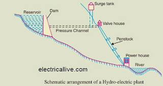
Although a hydro-electric power station simply involves the conversion of hydraulic energy into electrical energy, yet it embraces many arrangements for proper working and efficiency. The schematic arrangement of a modern hydro-electric plant is shown in Fig. .

The dam is constructed across a river or lake and water from the catchment area collects at the back of the dam to form a reservoir. A pressure tunnel is taken off from the reservoir and water brought to the valve house at the start of the penstock. The valve house contains main sluice valves and automatic isolating valves. The former controls the water flow to the power house and the latter cuts off supply of water when the penstock bursts. From the valve house, water is taken to water turbine through a huge steel pipe known as penstock. The water turbine converts hydraulic energy into mechanical energy. The turbine drives the alternator which converts mechanical energy into electrical energy.
A surge tank (open from top) is built just before the valve house and protects the penstock from bursting in case the turbine gates suddenly close* due to electrical load being thrown off. When the gates close, there is a sudden stopping of water at the lower end of the penstock and consequently the penstock can burst like a paper log. The surge tank absorbs this pressure swing by increase in its level of water.

Choice of Site for Hydro-electric Power Stations

The following points should be taken into account while selecting the site for a hydro-electric power
station :
(i) Availability of water. Since the primary requirement of a hydro-electric power station is the availability of huge quantity of water, such plants should be built at a place (e.g., river, canal) where adequate water is available at a good head.
(ii) Storage of water. There are wide variations in water supply from a river or canal during the year. This makes it necessary to store water by constructing a dam in order to ensure the generation of power throughout the year. The storage helps in equalising the flow of water so that any excess quantity of water at a certain period of the year can be made available during times of very low flow in the river. This leads to the conclusion that site selected for a hydro-electric plant should provide adequate facilities for erecting a dam and storage of water.
(iii) Cost and type of land.  The land for the construction of the plant should be available at a reasonable price. Further, the bearing capacity of the ground should be adequate to withstand the weight of heavy equipment to be installed.
(iv) Transportation facilities.  The site selected for a hydro-electric plant should be accessible by rail and road so that necessary equipment and machinery could be easily transported. It is clear from the above mentioned factors that ideal choice of site for such a plant is near a river in hilly areas where dam can be conveniently built and large reservoirs can be obtained.

Introduction And Importance To Electrical Energy

 Introduction To Electrical Energy


Energy is the basic necessity for the economic development of a country. Many functions necessary to present-day living grind to halt when the supply of energy stops. It is practically impossible to estimate the
actual magnitude of the part that energy has played in the building up of present-day civilisation. The availability of huge amount of energy in the modern times has resulted in a shorter working day, higher agricultural and industrial production, a healthier and more balanced diet and better transportation facilities.

As a matter of fact, there is a close relationship between the energy used per person and his standard of living. The greater the per capita consumption of energy in a country, the higher is the standard of living of its people.Energy exists in different forms in nature but the most important form is the electrical energy.
The modern society is so much dependent upon the use of electrical energy that it has become a part and parcel of our life. In this chapter, we shall focus our attention on the general aspects of electrical energy.

Importance Of Electrical Energy

Energy may be needed as heat, as light, as motive power etc. The present-day advancement in science and technology has made it possible to convert electrical energy into any desired form. This has given electrical energy a place of pride in the modern world. The survival of industrial undertakings and our social structures depends primarily upon low cost and uninterrupted supply of electrical energy. In fact, the advancement of a country is measured in terms of per capita consumption of electrical energy.

Must Read: Electrical Engineering Interview Questions

Electrical energy is superior to all other forms of energy due to the following reasons :

(i) Convenient form.Electrical energy is a very convenient form of energy. It can be easily converted into other forms of energy. For example, if we want to convert electrical energy into heat, the only thing to be done is to pass electrical current through a wire of high resistance e.g., a heater. Similarly, electrical energy can be converted into light (e.g. electric bulb), mechanical energy (e.g. electric motors) etc.

(ii) Easy control.The electrically operated machines have simple and convenient starting, control and operation. For instance, an electric motor can be started or stopped by turning on or off a switch. Similarly, with simple arrangements, the speed of electric motors can be easily varied over the desired range.

(iii) Greater flexibility.One important reason for preferring electrical energy is the flexibility that it offers. It can be easily transported from one place to another with the help of conductors.

(iv) Cheapness.Electrical energy is much cheaper than other forms of energy. Thus it is overall economical to use this form of energy for domestic, commercial and industrial purposes.

(v) Cleanliness.Electrical energy is not associated with smoke, fumes or poisonous gases. Therefore, its use ensures cleanliness and healthy conditions.

(vi) High transmission efficiency.The consumers of electrical energy are generally situated quite away from the centres of its production. The electrical energy can be transmitted conveniently and efficiently from the centres of generation to the consumers with the help of overhead conductors known as transmission lines.

Friday 8 May 2015

Factors Affecting Corona Loss

Corona loss depends upon numerous factors like system frequency,
system voltage, air density, surface and size of conductor etc.

These all factors are discribed as follows:-
A. System Frequency :- As we seen the in peeks formula and petersons
formula corona loss directly proportional to the system frequency.

B. System Voltage :- Electric field in the space arround the
conductors depends on potential difference between the conductors.
When potential difference increase the electric field increases and
therefore power loss due to corona increases.

C. Density of Air- Corona loss increases with decrease in air density
that means corona loss inversely proportional to density of air.
Corona loss in a transmission line which passes through a hilly area
than that when same line passes through plains. It is due to reduced
value of delta at high altitudes.

D. Conductivity of Air- Conductivity of air depends on number of ions,
per unit volume of air, size and charge per ion. These factors very
with altitude and atmospheric conditions. It means, in a rainy season,
numbes of ions increases and atmosphere becomes more conducting. When
conductivity increases, corona loss increases.

E. Conductor surface and Conductor Size- Potential gradient at the
surface of stranded conductor is greater than that for equipment solid
conductor, so corona loss is more for stranded conductor. Also corona
loss increases.

F. Load Current- Conductor heats up due to flow of load current.
Heating of conductor prevents the depositions of dew or snow on the
surface of conductor and reduce corona loss. During rains,heating of
conductor has no effect on corona loss, but after rain heating of
conductor accelerates the rate of drying of conductor surface. Time
for which rain drops, remain on surface is reduced and so corona loss
is reduced.

Saturday 2 May 2015

High Voltage Engineering Interview Question With Answer

Hello Friends. In last post we shared a lot of mcq on high voltage

engg. Now we are going to share interview question on high voltage

engg. In this post, breakdown in gases, liquids and solids is mostly

discussed. Lets start and enjoy interview question of high voltage

engineering.


Q.1 Mention the types of insulating materials which is used in high

voltage engineering?

Ans - Insulating materials are four types.

A. Solids

B. Liquids

C. Gases

D. Vacuun


Q.2 What are the salient properties of usual metals ?

Ans: These are:

A. Specific resistivity in ohm meter.

B. Temperature resistance coefficient.

C. Specific Gravity.

D. Tensile strength when used in overhead line.


Q.3 What are the usual materials for conductors used in high voltage

equipment and transmission lines?

Ans- Conductors are mostly fabricated from metals. Depending on the

equipment the following metals are found in high voltage work, gold,

silver, copper, aluminium, tin, lead, iron, nickel, chromium, and

others.


Q.4 What are the physical and electrical properties of important solid

insulations suitable for high voltage work?

Ans- The three important properties to look in solid insulation are

a. Dielectric strength which denotes kv/cm or kv/mm which the

insulation can withstand and which a designer will use based on

experience.

b. Dielectric constant.

c. Loss angle called delta which denotes the heating losss in the

insulation under the high voltage. The usual form in which this loss

is denoted by tan delta.

Saturday 18 April 2015

Interview Questions On Alternator

Hello Engineers.

Today we are sharing alternator interview questions with answer.

Q. 1. What are the two types of turbo-alternators ?
Ans.  Vertical and horizontal.

Q. 2. How do you compare the two ?
Ans. Vertical type requires less floor space and while step bearing is necessary to carry the weight of the moving element, there is very little friction in the main bearings. The horizontal type requires no step bearing, but occupies more space.

Q. 3. What is step bearing ?
Ans. It consists of two cylindrical cast iron plates which bear upon each other and have a central recess between them. Suitable oil is pumped into this recess under considerable pressure.

Q. 4. What is direct-connected alternator ?
Ans. One in which the alternator and engine are directly connected. In other words, there is no intermediate gearing such as belt, chain etc. between the driving engine and alternator.

Q. 5. What is the difference between direct-connected and direct-coupled units ?
Ans. In the former, alternator and driving engine are directly and permanently connected. In the latter case, engine and alternator are each complete in itself and are connected by some device such as friction clutch, jaw clutch or shaft coupling.

Q. 6. Can a d.c. generator be converted into an alternator ? If yes then how ?
Ans. Yes. A DC generator can be converted into an alternator. By providing two collector rings on one end of the armature and connecting these two rings to two points in the armature winding 180° apart.

Q. 8. Would this arrangement result in a desirable alternator ?
Ans. No

Q. 9. How is a direct-connected exciter arranged in an alternator ?
Ans. The armature of the exciter is mounted on the shaft of the alternator close to the spider hub. In some cases, it is mounted at a distance sufficient to permit a pedestal and bearing to be placed between the exciter and the hub.

Q. 10. Any advantage of a direct-connected exciter ?
Ans. Yes, economy of space.

Searches related to Basic MCQ Interview Questions On Alternator

electrical machines objective questions and answers pdf
electrical machines objective questions pdf download
mcq on alternator with answers
power factor of alternator at no load
objective questions on synchronous machines pdf
open wire test is used for?
synchronous machines questions and answers
synchronous machines objective questions with answers
Q. 11. Any disadvantage ?
Ans. The exciter has to run at the same speed as the alternator which is slower than desirable. Hence, it must be larger for a given output than the gear-driven type, because it can be run at high speed and so made proportionately smaller.